The basic configuration was chosen early for maximum simplicity. A straight cone, it was granted aerodynamic control via small strakes or fins (these fins are not typically shown on available drawings, as the external arrangement of the craft was classified). Aerodynamically, it was modeled after ballistic missile re-entry bodies, as the configuration had been extensively studied, was well understood, and provided the lift/drag ratio and low drag needed for the craft to perform synergetic maneuvers in the upper atmosphere. The craft would be either circular or slightly elliptical in cross section; circular would be easier to build, but elliptical would provide better aerodynamics.
A single pilot made up the basic crew; the pilot wore a spacesuit at all times, and relied on that suit for oxygen and pressurization. The pilot was to have an open cockpit when in space... his head would actually stick outside the craft. In the earliest concepts, the pilot was situated roughly in the middle of the craft, with a small payload bay ahead and the propellant tanks behind. These would all change.
An early tradeoff was between a collapsible, conventional single-bell nozzle rocket engine and a plug cluster. While the plug cluster would be more complex than the bell nozzle, it had numerous advantages, not least of which was that it was substantially shorter in length than a conventional engine of the same performance. Also, by having a multitude of small engines, thrust could be more efficiently throttled up and down by simply running a subset of the engines rather than trying to throttle a single engine (deep throttling of rocket engines has long proven difficult). The plug cluster arrangement was selected due to the notable increase in propellant volume. The system was pressure fed using helium; no turbopumps were needed. Aerojet provided assistance in the design of the individual thrusters and the complete plug cluster.
Figure 1: inboard views of the earliest desgins of the Spaceplane. Upper view shows a conventional single bell nozzle fitted, with extendable cones (as on the Peacekeeper ICBM) to reduce stored engine length. Note that the conventional engine, even with a collapsible nozzle, remains substantially longer than the plug cluster, shown below.
SRI International
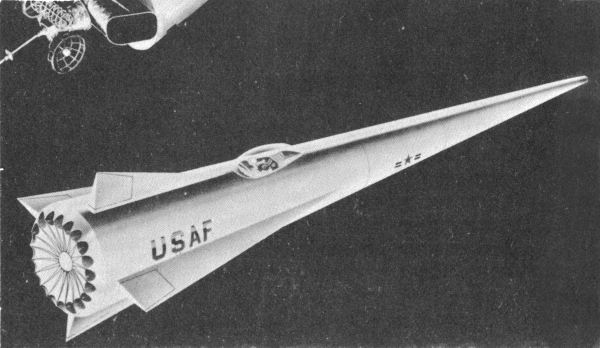
Figure 2: An artist's
conception of Aerojets early take on the Spaceplane. Note the inclusion of small wings and ventral and dorsal fins. Based on the astronauts head, this would be a rather larger Spaceplane... but that is not a certainty, given that
artists oftentimes take considerable liberties with scale. No matter how many
art classes they've taken, some artists' visions outweigh the realities.
Aerojet
Internal Tank Geometry Studies
The second major step in the refinement of the Spaceplane was in re-arranging the propellant tanks. They moved from the aft of the craft to amidships. This reduced the volume available; the fuels were the storable Nitrogen tetroxide (N2O4) and monomethyl hydrazine (MMH). Putting the tanks near the center of the craft meant that CG shift during engine burn was kept to a minimum, an advantage over the aft-tank arrangement.
One serious disadvantage to putting the propellant tanks in the extreme aft was that the diameter of the Spaceplane was quite small at the cockpit. While during orbital operations the pilot would sit up so that his head was out of the craft and he was in a normal sitting position, the pilot would have to fly "head down" during boost. This would be not only very disorienting, it would also be extremely uncomfortable.
Figure 3: Two conformal propellant tanks.
SRI International
Figure 4: Conformal oxidizer tank, spherical fuel tank
SRI International
Figure 5: Two spherical propellant tanks. While the logesnt of the configurations, this was selected due to being the lowest mass. A toroidal helium pressurant tank could go between the tanks. Elastomeric bladders would be used to expel the propellants.
SRI International
Figure 6: Conformal propellant tanks with integral bulkheads
SRI International
Engine Studies
An mumber of possible plug cluster configurations were studied. Plug Cluster Engine Configuration Number 3 was selected.
Figure 7: Plug Cluster Engine Configuration 1
SRI International
Figure 8: Plug Cluster Engine Configuration 2
SRI International
Figure 9: Plug Cluster Engine Configuration 3
SRI International
Figure 10: Plug Cluster Engine Configuration 4
SRI International
Figure 11: Plug Cluster Engine Configuration 5
SRI International
Part 2 will cover the final design in greater detail including primary and secondary propulsion systems, landing systems, launch systems, cockpit and instrumentation details and detailed internal views.
Issues of Aerospace projects Review can be purchased individually, or in any number. More on that HERE.

Back to APR Extras main page.

Aerospace Projects Review
11305 W 10400 N
Thatcher, Utah, 84337, U.S.A.
Contact me by e-mail
scottlowther AT ix DOT netcom DOT com.
You will need to delete the spam-blocking capitalized bits in the e-mail address. It's clumsy, annoying and definitely non-professional looking... but unfortunately, spammers read email addresses and target you for massive amounts of junk mail if you don't play little tricks.